| The main | Parts | Gas | Chart of nomograms | Reference information |
We set or is determined the following parameters:
k - adiabatic exponent;
Re - number Re;
T - temperature of gas, К;
R - gas constant, kg/m*kg.
G - the charge of gas, g/s;
d - diameter of an aperture orifice, mm;
F - the area of an aperture, mm2;
P0 - pressure before a orifice;
P1/P0 - the relation of pressure;
e - factor of the charge;
On the auxiliary diagram of definition of factor of the charge on an input in a orifice (еin)
F1/F0 - the relation of the area of an aperture of a orifice to the area of through passage section of the channel before a orifice.
On the auxiliary diagram of definition of factor of the charge on an output from a washer (еin)
F1/F0 - the relation of the area of an aperture of a orifice to the area of through passage section of the channel after a orifice.
The charge of gas at subcritical current:
G = e · F · P0 · [(2 · g/(R · T)) · (k/(k-1)) · ((P1/P0)2/k - (P1/P0)(k+1)/k]0,5
The charge of gas at supercritical current:
G = e · F · P0 · [(2 · g/(R · T)) · (k/(k+1)) · (2/(k+1))2/(k-1)]0,5
Critical difference:
[P1/P0]cr = [2/(k+1)]k/(k-1)
Formulas are submitted by the following complexes:
C-ex A = e · [2 · g/(R · T) ]0,5
For subcritical a mode - C-ex B = [(k/(k-1)) · ((P1/P0)2/k - (P1/P0)(k+1)/k]0,5
For supercritical a mode - C-ex B = [(k/(k+1)) · (2/(k+1))2/(k-1)]0,5
C-ex C = G/(F · P0)
adiabatic exponent: k = (Cv + R) / Cv = 1 + (R/Cv)
|
Gas |
Number of degrees of freedom |
Adiabatic exponent |
|---|---|---|
|
helium |
3 |
1.66 |
|
argon |
3 |
1.667 |
|
oxide carbon |
5 |
1.401 |
|
oxygen |
5 |
1.398 |
|
hydrogen |
5 |
1.408 |
|
nitrogen |
5 |
1.41 |
|
water steam |
6 |
1.33 |
|
carbonic gas |
6 |
1.305 |
|
ammonia |
6 |
1.313 |
|
methane |
6 |
1.315 |
For all options, the following parameter ranges are common:
d = 0.2 ... 1.9 mm P0 = 0.4 ... 35 kgf/cm2 Т = 200 ... 2500 К
|
e = 2...14 RTx10-3=0.2...7.5 G = 0 ... 400 g/s |
|
|
e = 2...14 RTx10-3=0.2...7.5 G = 0 ... 90 g/s |
|
|
e = 1...9 RTx10-3=0.2...15 G = 0 ... 90 g/s |
|
|
e = 1...9 RTx10-3=0.2...17 G = 0.01 ... 50 g/s |
|
|
e = 0.5...6.5 RTx10-3=0.2...17 G = 0 ... 45 g/s |
|
|
e = 0.5...4.1 RTx10-3=0.6...18 G = 0.005 ... 25 g/s |
|
|
e = 0.5...2.5 RTx10-3=0.6...17 G = 0 ... 23 g/s |
|
|
e = 0.2...1.8 RTx10-3=0.4...17 G = 0 ... 14 g/s |
|
|
e = 0.1...1.3 RTx10-3=0.2...18 G = 0 ... 9 g/s |
|
|
e = 0.1...0.5 RTx10-3=0.4...17 G = 0.01 ... 4.5 g/s |
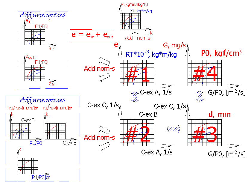
The basic system of nomograms consists of four nomograms. Nomograms 1 and 2 have additional nomogram systems consisting of three nomograms. For the first nomogram, this is the definition of the flow coefficient e (Y-axis), which is the sum of the flow coefficients at the inlet and outlet of the orifice, which in turn depend on the area ratio and the Reynolds number (10<Re<104). Also for the first graph, an additional nomogram is used to determine the product of RT (gas constant and gas temperature in K).
For the second nomogram, an additional system of nomograms is used to determine the C-ex B complex. This complex is calculated using different formulas for subcritical and supercritical flow regimes. Knowing the value of the adiabatic coefficient k, we determine the critical pressure drop for this washer from the lower graph of the additional system of nomograms. If the pressure drop across the washer chosen by us is less than [P1/P0]cr, then the flow is supercritical and the C-ex B complex is determined from the right auxiliary graph and depends only on k. If the difference we have chosen is greater than [P1/P0]cr, then the flow is subcritical and C-ex B is determined from the left nomogram and depends already on k and P1/P0.
graphic-analytical systems
Copyright © 2005-2022 All rights reserved