
| The main | Parts | Spring | Chart of nomograms | Reference Information |

|
|
d = 0.2 ... 9 (0.2 ... 1) mm Dm = 0 ... 12 mm Fmax-Fmin = 0...5 kgf L = 0 ... 50 mm
d = 0.2 ... 9 (1 ... 3) mm Dm = 5 ... 30 mm Fmax-Fmin = 5...20 kgf L = 0 ... 100 mm
d = 0.2 ... 8 (0.5 ... 4.5) mm Dm = 10 ... 45 mm Fmax-Fmin = 10...60 kgf L = 10 ... 110 mm
d = 1.1 ... 8.5 (1 ... 5) mm Dm = 10 ... 52.5 mm Fmax-Fmin = 10...60 kgf L = 50 ... 300 mm
d = 1.9 ... 8.5 (2 ... 8) mm Dm = 25 ... 75 mm Fmax-Fmin = 200 ...700 kgf L = 150 ... 500 mm
|
L - change of length of a spring under loading (spring stroke), mm;
d - diameter of a wire, mm;
Dm - average coiling diameter of wire, mm;
— - index of a spring;
G - shear modulus, kilogram-force/mm2 (kgf/mm2) (1 kgf/mm2 = 9.81 MPa);
i - number of coils;
Fmax-Fmin - difference between the maximal (matches to the maximum moving of a spring in the mechanism) and minimal (the length of a spring begins to change) loadings on a spring, kilogram-force (kgf), (1 kgf = 9,81 N);
Fmin1 - the minimal effort (40% from maximal Fmax1), kilogram-force (kgf);
Fmax1 - the maximal effort, kilogram-force (kgf);
Fmin2 - the minimal effort (60% from maximal Fmax2), kilogram-force (kgf);
Fmax2 - the appropriate maximal effort, kilogram-force (kgf).
2. We determine unknown parameters on agreed nomograms.
L = m ∑ i ∑ (Fmax - Fmin),
where L - elastic moving of a spring (spring stroke), mm;
m - spring compliance (one coil), mm/kgf;
i - number of working coils;
Fmin - bootstrop (initial loading), kgf;
Fmax - the maximal loading, kgf.
For tensioning springs, the initial load can be the preload of the spring during winding, Fmin = F0.
Spring compliance (one coil)
m = 8 ∑ C3 / (G ∑ d),
where G - shear modulus, kgf/mm2;
d - diameter of a wire, mm;
— - index of a spring
—=Dm / d.
| d, mm | Under 2.5 | 3 ... 5 | 6 ... 12 |
| — | 5 ... 12 | 4 ... 10 | 4 ... 9 |
For springs of square and right-angled cross-section condition performance is recommended D/b ≥ 4, where b is the side of the section perpendicular to the axis of the spring.
Shear modulus G for steel springs - (7.7 ... 8.5)*103 kgf/mm2 (1 kgf/mm2 = 9.81 MPa).
The minimal loading choosing on purpose of the spring
Fmin = (0.3 ... 0.8) Fmax.
Diagrams are constructed for two variants: F1min = 40% F1max and F2min = 60% F2max.
Value of a maximum load (limiting)
Fext = (1.05 ... 1.2) Fmax
Relative inertial backlash of a spring of compression
j=1-Fext/Fmax.
For springs of compression I and II classes j = 0.10 ... 0.25.
For springs of compression III class j = 0.15 ... 0.40.
For springs of a stretching j = 0.05 ... 0.10.
Spring limit deformation
Sext = Fext / b,
where b is the spring rate (the reciprocal of the compliance), kgf/mm (1 kgf/mm = 9.81 kN/m)
b = (Fmax - Fmin) / L.
Coiled spring length at maximum (limit) deformation
Lext = (i1 + 1 - i3) ∑ d,
where i1 - total number of spring turns
i1 = i + i2,
where i2 - number of support turns (for tensioning spring i1 = i);
i3 - number of ground coils of the compression spring.
So, the length of the compression spring in the free state
L0 = Lext + Sext.
Length of a cylindrical spring in the non-loaded condition:
X0=L0+2*Hh,
where Hh - height of one hook - (0.5 ...1) D.
After the application of maximal loading length of a spring of a stretching:
X=X0+L.
For springs of compression to calculation number of coils add on 0.75...1 coil for each end - i0 = i + (1.5...2).
Length of a spring of compression at contact of coils with the account grinding each end of a spring on 0.25d
X0=( i0 - 0.5 ) ∑ d.
Spring pre-deflection
Smin = Fmin / b.
Spring length at pre-deflection
Lmin = L0 - Smin.
For tensioning springs with trailers (hooks)
Lmin = L0 + Smin.
After applying the maximum load, the length of the tensioning spring is determined by simple summation
Lmax = Lmin + L,
where L - a spring stroke, mm.
Compression spring length after applying maximum load
Lmax = Lmin - L.
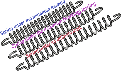
Figure - Three states of tension spring (Autodesk Inventor)
✺ ✺ ✺ ✺ ✺ ✺ ✺ ✺ ✺ ✺ ✺ ✺ ✺ ✺ ✺ ✺ ✺ ✺ ✺ ✺ ✺ ✺ ✺ ✺ ✺ ✺ ✺ ✺
|
|
F = 0 ... 25 kgf d = 0.2 ... 1.3 (0.2 ... 1) mm Dm = 1 ... 11 mm F = 25 ... 50 kgf d = 0.7 ... 2.1 (0.7 ... 1.9) mm Dcm = 3 ... 23 mm
F = 50 ... 300 kgf d = 1.0 ... 4.5 (1 ... 5) mm Dm = 5 ... 55 mm
F = 200 ... 1200 kgf d = 3.0 ... 9.0 (3 ... 9) mm Dm = 20 ... 70 mm
F = 500 ... 3000 kgf d = 4.0 ... 9.0 (5 ... 9) mm Dm = 20 ... 120 mm |
d - diameter of a wire, mm;
Dm - average coiling diameter of wire, mm;
— - index of a spring;
t - maximum (limit) permissible torsional stress ([τ]t), kgf/mm2 (1 kgf/mm2 = 9.81 MPa);
F - the maximal loading on a spring, kgf (1 kgf = 9.81 N).
tmax = 8 ∑ k ∑ F ∑ Dm / (3.14 ∑ d3) < [τ]t ,
where
[τ]t - limit permissible torsional stress, kgf/mm2;
F - loading, kgf;
k - coefficient, (curvature of a coils)
k = 1 + 1.45/—.
After transformations, we got the formula:
d = 1.6 ∑ [ k ∑ Fext ∑ C / [τ]t ]0.5,
where
Fext - as much as possible admissible (limiting) loading on a spring (on a nomograph - F), matching to a twisting ultimate stress, kgf;
C - index of a spring.
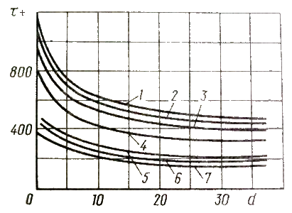
1 - tungsten wire; 2 - chrome vanadium wire; 3 - oil-hardened carbonaceous wire;
4 - Ůarbonaceous cold-drawn wire; 5 - monel metal wire; 6 - wire from phosphor bronze; 7 - special brass wire
Permissible stresses of twisting of materials of coil springs (X - d, mm; Y - [τ]t , MPa)
✺ ✺ ✺ ✺ ✺ ✺ ✺ ✺ ✺ ✺ ✺ ✺ ✺ ✺ ✺ ✺ ✺ ✺ ✺ ✺ ✺ ✺ ✺ ✺ ✺ ✺ ✺ ✺
|
|
d = 0.5 ... 1.9 mm Dm = 3 ... 11 mm i = 5 ... 62 m = 0.5 ... 2.5 g
d = 0.7 ... 2.5 mm Dm = 5 ... 21 mm i = 3 ... 24 m = 1 ... 5 g
d = 0.8 ... 3.5 mm Dm = 10 ... 50 mm i = 2 ... 38 m = 3 ... 23 g
d = 1.5 ... 7.0 mm Dm = 10 ... 50 mm i = 2 ... 46 m = 10 ... 90 g
d = 3.5 ... 9.0 mm Dm = 30 ... 50 mm i = 3 ... 22 m = 50 ... 250 g |
d - diameter of a wire, mm;
Dm - average coiling diameter of wire, mm;
i - number of working coils;
m - weight of a spring (without of a hooks), g
m = 19.25 ∑ 10-6 ∑ i ∑ Dm ∑ d2
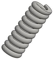
Figure - Compression spring (Autodesk Inventor)
✺ ✺ ✺ ✺ ✺ ✺ ✺ ✺ ✺ ✺ ✺ ✺ ✺ ✺ ✺ ✺ ✺ ✺ ✺ ✺ ✺ ✺ ✺ ✺ ✺ ✺ ✺ ✺
Springs, depending on the material of the wire, have different strengths. For example, springs made from chromium alloy steel are stronger than those made from steel alloyed with silicon, and the latter are stronger than those made from steel alloyed with manganese.
At the final stage of manufacturing of springs it is used spring hardening by aging in compressed condition. In need of increase of cyclic durability the spring is strengthened by fraction.
Defects are cleaned before the spring hardening by aging in compressed condition operation.
All springs with anticorrosive electrolytic coatings (chromium, nickel, cadmium, zinc, etc.) must be exposed to spring hardening by aging in compressed condition for at least 24 hours, regardless of whether spring were hardening by aging in compressed condition prior to coating or not. For non-critical springs of all classes and springs made of silicon-manganese bronze, the duration of spring hardening by aging in compressed condition is specified in the tables of the relevant standards.
Shot blasting the springs can greatly increase their endurance. As a result of shot blasting of the surface layers, the endurance limit of the springs increases by almost 50%.
Compression springs are wound by open winding with a gap between the turns of 10 ... 20% more than the calculated axial elastic displacements of each turn at maximum working loads. The tension springs are wound
so that the initial tension between the turns is provided. The value of this tension is selected from the range 25 ... 33% of the limit force for the spring, at which the stresses are close to the elastic limit.
Such winding is called closed.
For cold-wound springs, annealed or pre-prepared material is used. In the case of using an annealed material, the springs are hardened and tempered after winding.
When using pre-prepared material (mainly carbon steels), only spring tempering is applied after winding. There are three types of pre-prepared material: cold rolled, hard drawn, heat treated.
In the case of hot winding, the pre-heat treatment of the workpiece is not very important. After the springs are manufactured by hot winding, the springs are heat treated.
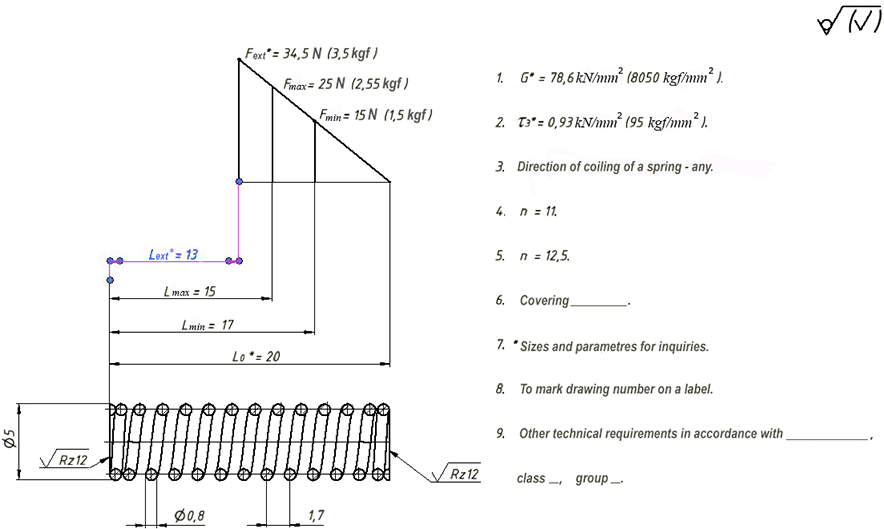
Figure - Compression spring characteristic and technical requirements (example of a compression spring drawing)
|
|
|
Figure - Drawings of tension and compression springs
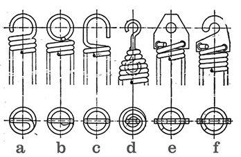
Drawing - Spring hooks
|
Material
|
Shear modulus, G∑103 kgf/mm2
|
|
Casting aluminum alloy |
2.4 - 2.7 |
|
Bakelite (no fillers) |
0.07 - 0.21 |
|
Phosphorous rolled bronze |
4.2 |
|
Duralumin after annealing at 3700— |
2.6 - 2.7 |
|
Iron Armco welding |
8.27 7.7 |
|
Cold Drawn Brass |
3.5 - 3.7 |
|
Cold drawn rolled copper |
4.9 |
|
Monel metal |
6.8 |
|
Lead |
0.7 |
|
Steel casting |
- |
|
Carbon steels |
7.7 - 8.5 |
|
Chrome-nickel steels |
8.1 |
|
Glass |
2.1 - 2.3 |
|
Textolite |
- |
|
Celluloid |
0.06 - 0.07 |
|
Rolled zinc |
3.2 |
|
Cast iron gray, white malleable |
4.5 2.9 - 4.0 |
Note.
1 kgf/mm2 = 9,81 MPa. For example, for spring steel G = 8 ∑ 103kgf/mm2 = 7,85 ∑ 104 MPa.
graphic-analytical systems
Copyright © 2005-2022 All rights reserved