Graphic-analytical calculation of beams of round and square section
Beam deflection under load
Graphic-analytical calculation of the deflection of a metal bar (pipe) of a round or square profile
In the given section four kinds of loadings and four various forms of section of a beam - a square pipe, a round pipe, a square
beam, a round beam are considered.
Calculated (calculation formulas are given): moment of resistance, moment of inertia, bending moment, maximum load (permissible load), deflection (bending).
With the help of graphic-analytical calculation, the geometric parameters of a metal beam of a round or square profile are selected for a given maximum load.
Formulas for Calculating Beam Deflection
Formulas for definition of the moment of resistance W and the moment of inertia J:
- for a square beam:
W
= h03 / 6,
J = h04 / 12;
- for a round beam:
W
= 0.0982 · d03,
J = 0.0481 · d04;
- for a pipe of a square structure:
W
= [ h04 -h14 ] / 6 · h0,
J = [ h04 - h14 ] / 12;
- for a pipe of a round structure:
W
= 0.0982 · [ d04 - d14 ] / d0,
J = 0.0491 · [ d04 - d14 ];
Formulas for definition - the permissible load Fmax, the bending moment М, the deflection у in the most dangerous section:
- for a square
beam:
M1
= F · L,
F1max = s· W / L, y
= F · L3 / [ 3 · E · J];
- for a round beam:
M2
= F · L / 2, F2max = 2 ·s·
W / L, y = F · L3 /
[ 8 · E · J ],
F = q · L (q - linear load);
- for a round beam:
M3
= F · L / 4, F3max = 4 ·s·
W / L,
y = F · L3 / [ 48 ·
E · J ];
- for a pipe of a round structure:
M4
= F · L / 8, F4max = 8 ·s·
W / L, y = 5 · F · L3
/ [ 384 · E · J ],
F = q · L.
A bar - is a construct in which one of the three dimensions that determine its dimensions (length) is much larger than the other two.
When considering the processes of tension or compression, the beam can be called a rod, when bending - beam.
The rod is called thin-walled if the ratio of the width of the walls to the thickness is more than 5...10.
The cross section of a thin-walled rod is called its profile.
To select the optimal combination of a given load, allowable load, deflection, material and dimensions of the beam, moment of inertia, moment of resistance, bending moment,
we use the graphic-analytical method and form a system of nomograms.
|
System
of nomograms #1
F1max
= 60 ... 300 kgf
F2max
= 120 ... 600 kgf
F3max
= 240 ... 1200 kgf
F4max
= 480 ... 2400 kgf
L
= 2 ... 5 m
F
= 30 ... 1600 kgf
h0
= 50 ... 75 mm
h1
= 20 ... 63 mm
d0
= 55 ... 85 mm
d1
= 20 ... 70 mm
W
= 6 ... 54 cm3
s=700
... 3000 kgf/cm2
E·105
= 4 ... 21 kgf/cm2
J
= 30 ... 174 cm4
System
of nomograms #2
F1max
= 10 ... 400 kgf
F2max
= 20 ... 800 kgf
F3max
= 40 ... 1600 kgf
F4max
= 80 ... 3200 kgf
L
= 1 ... 2.5 m
F
= 40 ... 1800 kgf
h0
= 35 ... 65 mm
h1
= 20 ... 53 mm
d0
= 40 ... 70 mm
d1
= 20 ... 56 mm
W
= 1 ... 36 cm3
s=
700 ... 3000 kgf/cm2
E·105
= 4 ... 21 kgf/cm2
J
= 11 ... 138 cm4
System
of nomograms #3
F1max
= 20 ... 500 kgf
F2max
= 40 ... 1000 kgf
F3max
= 80 ... 2000 kgf
F4max
= 160 ... 4000 kgf
L
= 0.5 ... 1.1 m
F
= 50 ... 1800 kgf
h0
= 25 ... 55 mm
h1
= 15 ... 46 mm
d0
= 30 ... 70 mm
d1
= 15 ... 49 mm
W
= 1 ... 36 cm3
s=
600 ... 3000 kgf/cm2
E·105
= 2.5 ... 21 kgf/cm2
J
= 3 ... 138 cm4
|
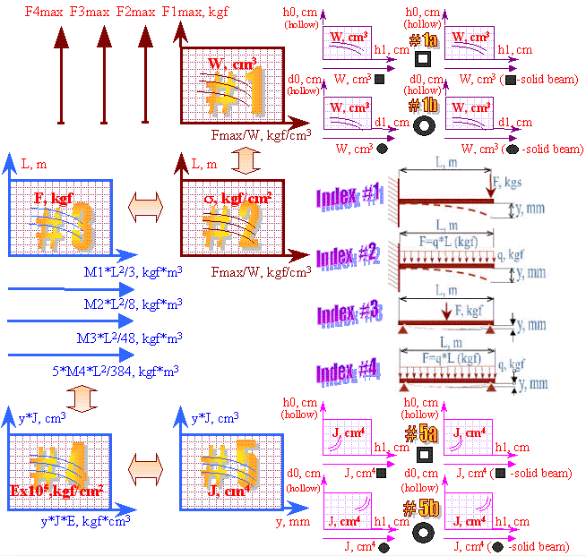
Beam calculation parameters for deflection (bending)
Fmax
- maximal loading, kgf;
W
- moment of resistance, cm3;
s
- bending stress, kgf/cm2;
L
- length of a beam, m;
F
- loading in dangerous section, kgf;
E
- modulus of elasticity, kgf/cm2;
J
- moment of inertia, cm4;
у
- deflection in dangerous section, mm;
h0
- external dimension of a square pipe (beam), cm;
h1
- internal dimension of a square pipe, cm;
d0
- external diameter of a pipe (beam), cm;
d1
- internal diameter of a pipe, cm;
Red color on illustration allocates determined parameters of a beams |
The procedure for grapho-analytical calculation of a beam for deflection
1. We find on the graphs the known values of the parameters (calculated or initial - in the first approximation).
2. The unknown values of the remaining parameters are found using adjacent nomograms.
Examples - Beam Deflection Calculation
Example 1 The horizontal bar is a steel pipe (steel 20X) with a length L = 1 m with an outer diameter d0 = 34 mm and an inner diameter d1 = 26 mm with loosely fixed ends.
Athlete weight - F=100 kg. In this case, we have the third loading option with a force of 100 kgf.
Using the nomogram No.1b we determine the moment of resistance for a given profile - W=2,7 cm3.
Allowable bending stress for a given pipe material is taken s=1500 kgf/cm2.
On the nomogram No.2 we find Complex А=15100 кгf/cm3.
On the nomogram No.1 we determine the value of the limit force for the third loading scheme F3max : F3max = 158 кg.
Further on the nomogram No.3 we determine the intermediate value - М33·L2/4 = 33 kgf*m3.
Since for the third loading scheme М33·L2/4 = y·J·E, find on the nomogram No. 4 the value Complex B = 17 cm5
(the value of the modulus of elasticity of steel is taken Е=20·105kgf/cm2).
Using the nomogram No. 5b we determine the moment of inertia for a given profile - J = 4,5 cm4.
So, for a given moment of inertia J, the displacement value (deflection) у = 26 mm.
As a result of this calculation for the bend, the following result was obtained.
Maximum load - 158 kg. The horizontal bar under the weight of an athlete of 100 kg will bend by 27 mm.
Let's carry out the calculation for the given conditions using an engineering calculator. As a result of an exact calculation, we get:
W = 2,54 cm3;
F3max=152,4 kgf; J=4,32 cm4; у=24 mm.
|
Example 2.
The frame with harrows attached to it has weight 900 kg.
The entire structure is cantilevered on several square profile beams. Console length 3 m.
Perform beam deflection calculations. Determine the number of beams and section parameters.
|
Example 3.
How many bags weighing 50 kg each can be evenly folded onto two square pipes with an outer diameter of 55 mm and an inner diameter of 40 mm,
placed on two supports with a distance between them of 2.7 m?
Determine the deflection of the pipes if you lay a fourth of this number of bags.
Specified pipe material with characteristics -
s=1300 kgf/cm2,
E=2x10⁶ kgf/cm2. |
|
We take the number of beams equal to four.
Profile options - h0 = 70 mm, h1 = 50 mm.
Then each beam has a load of 225 kgf from the weight of the frame with harrows (1 loading option).
Choose a material with the following parameters -
s=2200 kgf/sm2,
E=2x10⁶ kgf/cm2.
|
We have the fourth loading scheme.
We find the value of the maximum allowable load. We accept the condition - the load under the bags should be ~ 20% less than the maximum allowable load.
We increase the obtained value by 2 times (by the number of pipes).
|
| Graph-analytical method |
Calculator |
Graph-analytical method |
Calculator |
|
W
= 42 cm3
J
= 147 cm4
F1max
= 305 kg
y
= 70 mm |
W
= 42,29 cm3
J
= 148 cm4
F1max
= 310,12 kg
у
= 68,4 mm |
W
= 20 cm3
J
= 55 cm4
F3max
= 768 kgf
Fsym
(80% F3max) = 1228,8 kgf
Number of bags - 24 pieces
F
= 307 kg
y =
77 mm |
W
= 19,97 cm3
J
= 54,9 cm4
F3max
= 769,2 kg
Fsym
(80% F3max) = 1230,7 kgf
Number of bags - 24 pieces.
F
= 307,7 kg
у
= 72 mm |
Reference information for beam deflection calculation
Permissible stresses are the maximum values of the design stresses that can be allowed in a dangerous section,
while ensuring the reliability of the part required under operating conditions.
Table 1
- Permissible stress during bending of steels of different grades under the influence of a load (constant, variable, alternating) after various types of heat treatment
| Material |
Heat treatment |
Allowable bending stress, kgf/cm2 |
| static load |
variable load |
load is sign-variable |
| |
|
Steel 15
|
Normalization |
950
|
800
|
600
|
| Carburizing with water quenching and subsequent tempering for hardness HRC 56 - 62 |
1500
|
1150
|
800
|
|
Steel 35
|
Normalization |
1350 |
1100 |
800 |
| Improvement |
2100
|
1550
|
1000
|
| Hardening in water and then tempering for hardness HRC 33-43 |
2700 |
2000 |
1350 |
Steel 45 |
Annealing |
1350 |
1100 |
800 |
| Normalization |
1550 |
1250 |
950 |
| Improvement |
2200 |
1750 |
1300 |
| Hardening in water and then tempering for hardness HRC 38-48 |
3000 |
2200 |
1450 |
Steel 20X |
Normalization |
1500 |
1150 |
800 |
| Improvement |
2100 |
1550 |
1000
|
| Carburizing with oil quenching and hardness tempering 56-62 |
3000 |
2200 |
1400 |
Steel 40X |
Annealing |
1800 |
1400 |
1000 |
| Improvement |
2700 |
2000 |
1350 |
| Oil quenching followed by hardness tempering HRC 37-41 |
4300 |
3100 |
1900 |
| Oil quenching followed by hardness tempering HRC 46-50 |
5100 |
3700 |
2300 |
12XH3 |
Normalization |
1900 |
1400 |
950 |
| Carburizing with oil quenching and hardness tempering HRC 55-61 |
3200 |
2400 |
1550 |
Unit conversion: 1 kgf/cm2 = 98,0665 kPa
Table 2
- Modulus of elasticity of various materials
|
Material
|
Modulus of elasticity (Young's modulus)
Е·105,
kgf/cm2
|
|
Aluminum alloy casting
Duralumin after annealing
at 370 0С
В95-ТI
-
АК8-TI,
Д16-Т -
АМг6
-
|
6.7 - 7.2
7 - 7.5
7
7.2
6.8
|
|
Bakelite (without fillers)
|
0.2 - 0.6
|
|
Phosphor bronze rolled
|
11.5
|
|
Titanium alloy
- ВТ6
|
11.2
|
|
Iron Armco
welding
|
21
16 - 20
|
|
Magnesium alloys -
ВМ65-I, МА2-I
|
4.2
|
|
Brass, cold drawn
|
9.1 - 9.9
|
|
Cold drawn rolled copper
|
11 - 13
|
|
Monel metal
|
17.6
|
|
Lead
|
1.7
|
|
Steel casting
|
17.5
|
|
Carbon steels
|
20 - 21
|
|
Nickel-chromium steel
-
30ХГСНА
-
12Х2НВФА
|
20 - 21
19.5
20
|
|
Glass
|
4.9 - 6.3
|
|
Textolite
|
0.6 - 1
|
|
Celluloid
|
0.17 - 0.2
|
|
Zinc rolled
|
8.4
|
|
Cast iron grey, white
malleable
|
15.5 - 16
до 15.5
|
|
Nickel |
21 |
|
Tungsten |
36 |
|
Gold |
1.6 |
|
Nylon |
0.5 |
|
Bone |
2 |
|
Fiberglass - АФ -10В |
2.44
|
Modulus of elasticity (Young's modulus [Thomas Young, 1773 - 1829] ) - coefficient of proportionality between F/S (force/cross-sectional area) and relative elongation (tension) dL/L,
obtained for a certain material.
graphic-analytical systems
The contact information. E-mail:nomogramka@gmail.com
Copyright ©
2005-2022 All rights reserved